Plant Details
PLANT CONFIGURATION :The plant configuration as envisaged is as given below.
Sponge iron plants of 350TPD coal based rotarykilns 1,05,000 tons per annum capacity 2nos
Power plants based on waste heat recovery from sponge iron plants 8MW 2nos
Power plants based on waste char/coal fines from sponge iron plants 8/16MW 1no
Steel plant with induction furnace 10tons capacity 4nos,ladle refining furnaces 20tons capacity 2nos,continuous billet casting machine.
Rolling mill for wire rods, TMTbars,structuralsteel of 2,50,000 tons per annum.
In the first phase one 350 TPD rotary kiln and 8MW power plant have been commissioned and are operating smoothly .
.
SPONGE IRON PLANT
Sponge iron plant or Direct Reduction Plant (DRP) is designed to produce 350tons of sponge iron per day in a rotary kiln using iron ore, non coking coal and dolomite as the raw materials.
The plant consists of the following sub divisions.
Raw material preparation plant
Direct reduction plant
Raw material preparation plant
The basic raw materials for the production of sponge iron are iron ore, non coking coal and dolomite.
Iron Ore:
Iron ore is the source of iron and available in oxide form namely hematite(Fe2O3). As only oxygen can be removed from the iron ore during the process of making sponge iron iron,ores rich in iron content of 65percent and above is preferred.
We source iron ore from our group company from Barbil mineral rich area of Odisha state. We procure sized iron ore of 5-18mm for our requirement. As some degradation takes place during transportation and handling, we have made the provision of screening the iron ore for the removal of undersize 5mm and oversize 20mm in the iron ore circuit of raw materialpreparation plant. The iron ore circuit consists of the following
Ground hopper.
Belt conveyors
Vibratory screen
Iron ore finesbin
Day Bin for Iron ore
Non Coking Coal:
Coal provides the necessary heat requirement of the process as well as for the generation of reducing gases for the removal of oxygen from the iron ore. Generallycoals with volatile matter 26percent minimum and fixed carbon above 45percent are preferred. In view of good reactivity for the generation of reducing gases, non coking coals are selected for use as reductant in coal based rotary kilns.
We procure coal from MahanadhiCoal Ltd and imported coal from South Africa/Indonesia. As the coal received is of 0to 250mm size in case of MCL coal and 0-50mm in case of imported coal, we have installed crushing and screening facility for the coal. Based on the process requirement , the received coal is crushed and screened in to three size fractions 0-4mm.4-18mm,4-20mmin the coal circuit of raw material preparation plant. The coal circuit consists of the following
Ground hopper
Belt conveyors
Primary crusher
Secondary crusher
Vibratory screens
Coal fines bin
Day bins for fine coal ,coarse coal,feed coal-1 ,feed coal-2
Dolomite:
While coal is being used as reductant, the sulphur present in the coal can cause sulphur pick up in the product sponge iron. As sulphur in steel can cause development of cracks during the hot processing of steel,sulphur in sponge iron is to be controlled with in 0.03percent max. Dolomite in the form of fine grains is used as a desulphuriser. Dolomite with CaO 25 – 30 percent ,MgO 15-20 percent and silica not exceeding 8 percent is generally chosen in this process.
We procure dolomite of the above chemical composition in the size range of 2-8mm from Chattisgarh State. The dolomite circuit consists of the following
Emergency ground hopper
Belt conveyor
Day bin for dolomite
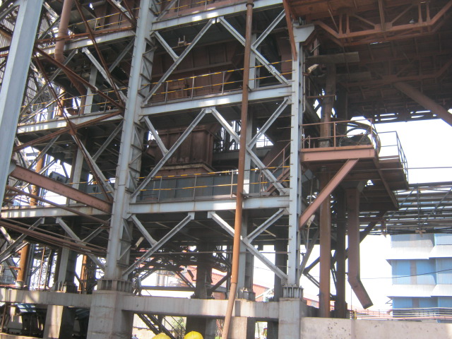
DIRECT REDUCTION PLANT
Flow chart of direct reduction plant
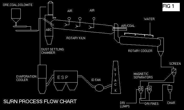
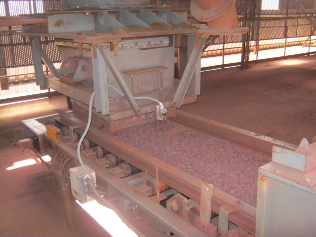
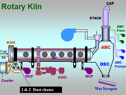
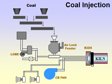
Sized iron ore, feed coal-1,feed coal-2,dolomite,corse injection coal, fine injection coal are stored in the day bins.Electronicweigh feeders have been provided to ensure accurate dosing of the raw matrials for the proceeding in the rotry kiln of 4.3meters in diameter and 72meters long inclined at 2,5 percent.
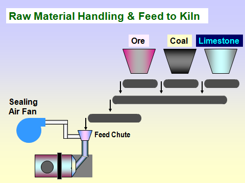
Sized iron ore, feed coal-1 and feed coal -2 and dolomite are fed continuously to the charge end of Rotary Kiln inclined at 2.5percent.corase Coal and fine coal mixed as per the process requirement is also injected through an injection pipe at the discharge end of Kiln. Due to the inclination and rotation of Kiln at 0.4rpm, the charge material moves along the length of Kiln where it is discharged continuously after processing. To supply heat for the process air is blown into the Kiln through central burner and air pipes mounted on the Kiln shell. As the charge moves along the Kiln, it is heated by the gases which flow in counter current direction.
The first section, approximately half of Kiln is called preheating zone where iron ore, coal and dolomite are heated to reaction temperatures 1230oC. Generally the preheating of raw materials takes place in 2-3 hours. The second half of Kiln is called reduction zone where major amount of oxygen contained in the iron ore is removed leaving metallic iron (Fe ). The travel time in the reduction zone of the rotary kiln is 6-8 hours.
The following chemical reactions take place in different zones of rotary Kiln as given below.
CaCO3/MgCO3 = CaO/MgO+CO2
CO2+C = 2CO
3Fe2O3+CO=2Fe3O4+CO2
Fe3O4+CO=FeO+CO2
FeO + CO=Fe+CO2
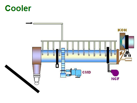
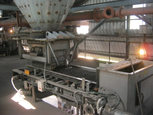
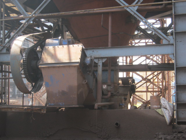
The reduced iron ore i.e. SPONGE IRON from rotary Kiln with other contaminants like non magnetic char/stone pieces gets discharged into a Rotary Cooler at a temperature of 950-1000deg C. The rotary cooler is 2.2 meters in diameter and 50 meters long inclined at 2.5 percent and rotating at 0.8-1.2 rpmThe sensible heat of the matirials will be dissipated indirectly by water sprayingof the order of 500-550 m3/hour on the outside of Cooler Shell. The material gets cooled to around 1000C and the travel time in the cooler is 2 hours..
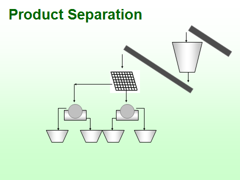
The cooler discharge materials consisting of sponge iron, char, dolochar and other contaminatscoming out of cooler is screened in a vibratory screen to 0-4mm and 4-20 mm and plus 20mm. the 4-20mm matireials are proceesed in lumps drum type rotaing magnetic separator. The 0-4mm areprocressed in double stge fines drum mageniticseparor to ensure the purity of iron. The magnetic sponge lumps and the magnetic sponge iron fines are stored in the product storage bins. The nonmagnetics char and dolochar are also stored in waste product bins. Plus 20 mm material in the cooler discharge is generally accretion pieces and collected separately from the chute.
DSC WET SCRAPPER
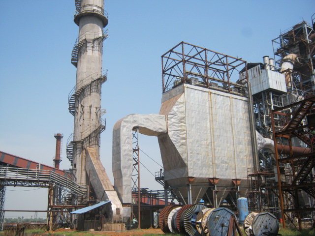
The waste gases 80000-85000Nm3/hour with gas velocity o15 to 20m/sec leaving rotary Kiln enter a maasivesize a Dust Settling Chamber (DSC). Due to sudden expansion in volume of the gases, the velocity drops to 103m/sec. in view of sudden dropn in velocity dthe dust particles of size more than 100 microns settles down in wet scrapper attached beneath the dust settling chamber. Then the waste gases pass to an After Burning Chamber (ABC) where the combustibles like carbon, soot particles are burnt out in two zones. Water spray nozzles have been provided to control the temperature of gases with in 950 deg C. The gases that are coming out of after burning chamber a 950 deg.C are cooled in a Gas conditioning tower using a fine mist of water spray at 40bar pressure to around 2000C. some part of dust below 100 microns settles at the conical bottom of gas conditioning tower and collected through a wet scrapper. Alternately the gases pass through a Waste Heat Recovery Boiler (WHRB) for steam generation of 35tons/hour at a pressure of 64kg/cm2 at a temperature0f 485 deg.C
GCT WET SCRAPPER
ELECTRO STATIC PRECIPITATOR
The waste gases leaving the WHRB or Gas Conditioning tower at a temperature of 200deg. C pass gas distribution plate of Electro Static Precipitor. The purpose of the GD plate is to ensure uniform flow of the gases in the entire cross section of ESP for proper collection of dust. While the gas pass through the gas passage of 400mm in width, the dust particles are ionized by the emittingelectrodes charged with high voltage DC rectifier. The ionized dust particles get attracted in the positive collecting electrodes. The layer of dust is periodically removed by shaking the collecting plates with rapping hammers. The collecteddust in the pyramidal hoppers of ESP is pneumatically conveyed to the fly ash silo.We have provided liberally designed ESP with 14gas passage, 4200 square meter collection areadistributed in three fields to ensure that the emission level is below 50mg/Nm3 of waste gas. The cleaned waste gases as per the norms of PCB are let into the atmosphere through the 75 meter height concrete Chimney.The 250 KW induced draft fan provides the kinetic energy for the flow of gases from the rotary kiln, dust settling chamber, after burning chamber, gas conditioning tower/WHRB, electro static precipitator.
UTILITIES
The water requirement of the plant is estimated as 3900 m3/day to be obtained from the river Brahmani at a distance of 8KM. Daily requirement of the water at present for the first stage of the plant is 1200m3/day from this source through pipelines and stored in the raw water tank inside the plant. Raw water is clarified in a Clarifier with flocculants to minimize the turbidity and stored in clarified water tank. Water is pumped to the make water tank in the DRP or to the DM plant in the Power plant as per the daily requirement.
To meet the need of compressed air for the bag filters and for the plant operational requirements 6 nos of 572 CFM screw compressors and 4 nos220 CFMscrew compressors have been provided.
INPUT/OUTPUT
The material balance for the input raw materials and output product/waste products was calculated as given below.
| Input raw materials in tons | Iron Ore: | 456.00 | |
| Coal: | 360.00 | ||
| Dolomite: | 7.2 | ||
| Total: | 823.20 |
Product /Solid Waste/Waste Gases in tons
| Sponge Iron | 304.61 | 36.87% |
| Char | 93.64 | 11.34% |
| Bag filter Dust | 20.00 | 2.42% |
| Wet Scrapper Dust | 5.00 | 0.60% |
| ESP/GCT Dust | 49.79 | 5.42% |
| Accretion | 7.51 | 0.91% |
| O2 Loss | 114.21 | 13.82% |
| LOI | 2.28 | 0.30% |
| VM from Coal | 82.80 | 10.02% |
| Moisture from Coal | 32.40 | 3.92% |
| Moisture from Ore | 4.56 | 0.55% |
| Burning of Carbon | 111.34 | 13.48% |
| Dolomite cal. | 2.88 | 0.35% |
| Total output | 826.02 | 100% |
| Input-Output | +2.82 | +0.34% |
| Solid Wastes | 170.94 | 20.69% |
| Waste Gases | 350.47 | 42,42% |